

Does A Inductor Ever Change Magnetic Flux Direction

Inductance
Inductance is a holding of an electric excursion past which a changing magnetic field creates an electromotive force, or voltage, in that circuit or in a nearby circuit. Inductance is too defined equally the belongings of an electrical circuit that opposes any change in current. In 1831, Michael Faraday, an English scientist, discovered that a irresolute magnetic field in a circuit induced a current in a nearby excursion. Joseph Henry, an American scientist, independently made this discovery at about the same time. The generation of an electromotive strength and current by a changing magnetic field is called electromagnetic induction. The operation of electric generators is based on the principal of inductance.
Magnetic Field LinesIn order to better understand inductance, information technology is helpful to have an understanding of magnetic field lines. All magnets are surrounded by a magnetic field, also called magnetic flux. A magnetic field can exist thought of consisting of lines of force, or flux lines. The forces of magnetic attraction and repulsion movement along the lines of strength. The blueprint of magnetic field lines can be observed in our Magnetic Field Lines Interactive Java Tutorial.
Faraday fabricated his discovery of electromagnetic consecration with an experiment using 2 coils of wire wound around opposite sides of a ring of soft atomic number 26 similar to the experiment setup in Figure one below.
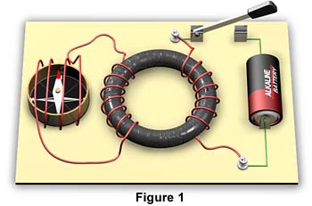
The showtime whorl on the right is attached to a battery. The 2d coil contains a compass, which acts as a galvanometer to find current flow. When the switch is airtight, a current passes through the showtime coil and the iron band becomes magnetized. When the switch is beginning airtight, the compass in the 2nd coil deflects momentarily and returns immediately to its original position. The deflection of the compass is an indication that an electromotive force was induced causing electric current to flow momentarily in the second coil. Faraday too observed that when the switch is opened, the compass once more deflects momentarily, but in the opposite direction.
Faraday was aware that that a coil of wire with an electric current flowing through information technology generates a magnetic field. Therefore, he hypothesized that a irresolute magnetic field induces a current in the second coil. The closing and opening of the switch cause a magnetic field to change: to expand and collapse respectively. You can conduct Faraday'due south experiment at our Faraday'due south Experiment Interactive Java Tutorial.
Faraday demonstrated that his hypothesis was right past moving a simple bar magnet dorsum and along inside a coil. He observed that a current was induced in the coil only while the magnet was in movement. He also observed that a electric current was induced in the coil when the coil itself was moved near a stationary permanent magnet. He discovered that it is the relative motion between a usher and a magnetic field that produces electric current. To generate current, either the conductor can movement through the field, or the field tin move past a conductor. In order for electromagnetic induction to occur, there must be a change of magnetic flux. Conduct this experiment at our Faraday'south 2nd Experiment Interactive Java Tutorial.
The human relationship between changing magnetic flux and induced electromotive force is known equally Faraday'due south law of electromagnetic induction:
The magnitude of an electromagnetic forcefulness induced in a circuit is proportional to the rate of change of the magnetic flux that cuts across the excursion.
Mathematically, Faraday's constabulary is written as:
E = - (DF/Dt)
where E is the induced electromotive strength in volts, DF is the change in magnetic strength in webers, and Dt is the amount of time in seconds in which the change in magnetic force takes place.
From the above formula we see that the amount of induced voltage is adamant past two factors:
- The amount of magnetic flux
The greater the number of magnetic field lines cut beyond the conductor, the greater the induced voltage. - The rate at which the magnetic field lines cut across the conductor
The faster the field lines cut across a conductor, or the conductor cuts across the field lines, the greater the induced voltage. You tin observe this by varying the speed at which you motility the magnet in our Faraday'southward second Experiment Interactive Java Tutorial.
The minus sign in Faraday'south law refers to the direction, or polarity, of the induced voltage. In 1833, the Russian physicist Heinrich Lenz discovered the directional relationships amongst the forces, voltages, and currents of electromagnetic induction. Lenz'southward law states:
An induced electromotive forcefulness generates a current that induces a counter magnetic field that opposes the magnetic field generating the current.
For instance, when an external magnetic field approaches a ring shaped usher, the current that is produced in the ring volition induce its own magnetic field in opposition to the approaching external magnetic field. On the other hand, when the external magnetic field moves away from the ring, the induced magnetic field in the ring reverses direction and opposes the alter in the management of the external magnetic field. You tin find Lenz's police force in activeness at our Lenz'southward Law Interactive Java Tutorial.
We know that current period in a conductor produces a magnetic field around the conductor. When the current is increasing, decreasing, or changing management, the magnetic field changes. The magnetic field expands, contracts, or changes management in response to the changes in current period. A changing magnetic field induces an boosted electromotive forcefulness, or voltage in the conductor. The induction of this additional voltage is called cocky-induction, because it is induced inside the conductor itself. The direction of the cocky-induced electromotive forcefulness, or voltage, is in the opposite direction of the electric current flow that generated information technology. This is consequent with Lenz'due south law, which can be expressed equally follows:
An induced electromotive force (voltage) in any circuit is always in a direction in opposition to the current that produced it.
The event of self-induction in a circuit is to oppose any change in current flow in the circuit. For example, when voltage is applied to a circuit, current begins to flow in all parts of the circuit. This current induces a magnetic field effectually it. Every bit the field is expanding, a counter voltage, sometimes chosen back voltage, is generated in the circuit. This back voltage causes a current flow in the opposite direction of the principal current catamenia. Inductance at this phase acts to oppose the buildup of current. When the induced magnetic field becomes steady, it ceases to induce back voltage.
When the electric current in a circuit is switched off, the induced magnetic field begins to plummet. As the field is collapsing, it generates voltage in the direction that momentarily prolongs the main current menses. When the induced magnetic field is fully complanate, the induced voltage and electric current flow finish. Again, self-induction opposes changes in current flow. It opposes the buildup, and delays the breakdown, of electric current. Yous can see the effects of self-inductance on current menstruum in our Self-Inductance Interactive Java Tutorial.
In Faraday's experiment with two coils on a conducting fe band, he discovered that a irresolute magnetic field in one coil induces an electromotive forcefulness, or voltage, in the second gyre. This phenomenon is called common inductance. Mutual inductance occurs when a irresolute magnetic field in one excursion induces voltage in a nearby circuit.
Consistent with Lenz's law, the management of the induced electromotive force, or voltage, is in the contrary management of the current catamenia that generated it. Looking at Faraday'southward experiment again below, we find that when voltage is practical to the coil on the right, a magnetic field is induced in the fe ring. As the field is expanding, a voltage is generated in the second scroll on the left. This secondary voltage causes a electric current period in the second coil. This secondary current flow is in the opposite direction of the current flow of the first curl. When the induced magnetic field in the ring becomes steady, electric current ceases to flow in the 2nd ringlet.
When the current in the first coil is switched off, the induced magnetic field in the ring begins to collapse. Every bit the field is collapsing, information technology over again generates voltage in the second ringlet. The resulting current period in the second coil is in the opposite direction of the previously induced current. When the magnetic field in the ring is fully collapsed, the induced voltage and current flow in the secondary curl ceases. You lot tin can acquit this experiment at our Faraday'southward Experiment Interactive Coffee Tutorial.
Inductors are electrical devices that are designed to provide inductance in a circuit. An inductor is simply a curl of wire. Self-inductance occurs in a circuit even when conductors are perfectly straight. Nevertheless, self-inductance in a straight conductor is very modest. Inductance is much more significant when conductors are coiled, because the magnetic field of each plow of the coil cuts across nearby turns of the coil. To increase inductance, an inductor may accept an iron core. Putting iron inside a coil greatly increases the strength of its magnetic fields.
Factors Affecting Inductance of a CoilThe inductance of a coil is affected past three factors:
- The number of turns in the coil
The greater the number of turns in a coil, the greater the inductance. This is truthful because the more turns at that place are in a curlicue, the greater the number of magnetic field interactions. - The area of the cross section of the coil
The greater the cross-sectional area of a coil, the greater the inductance. This factor is closely related to the number of turns in a curl. Information technology includes consideration of the spacing of the turns. Since a magnetic field becomes weaker as it moves out, turns that are closely spaced provide for interactions where the fields are strongest. - The permeability of the core
Permeability refers to the ability of a textile to conduct magnetic lines of force. Atomic number 26 has much greater permeability than air. Therefore, a coil with an fe cadre has greater inductance than one with a core containing just air.
Faraday's Law tin can be used to determine the total induced electromotive force, or voltage, in a ringlet. Assuming that the turns of the whorl are closely wound, the full inducted voltage of a curl can exist calculated using the following formula:
E = - N (DF/Dt)
where E is the induced electromotive strength in volts, N is the number of turns in the coil, DF is the change in magnetic force in webers, and Dt is the amount of fourth dimension in seconds in which the change in magnetic strength takes place.
Measurement of InductanceThe symbol for Inductance is the capital letter L in honor of Heinrich Lenz. The unit of measurement for inductance is the henry, named after Joseph Henry, and abbreviated as h. One henry of inductance exists when one volt of electromotive strength is induced when the current is irresolute at the rate of one ampere per second. Mathematically, this is written equally:
L = East /(DI/Dt)
where L is inductance in henries, Due east is induced electromotive strength in volts, DI is the alter in current in amperes, and Dt is the amount of time in seconds in which the alter in current takes place.
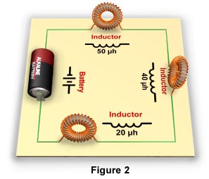
Inductors in Serial CircuitsA series circuit is a circuit in which the current has just 1 path. In a series circuit, all of the current passes through each of the components in the circuit. The circuit in Figure 2 has three inductors in series.
If the inductors are shielded, or far enough autonomously to preclude mutual inductance, the total inductance of the circuit is cumulative. The total inductance of such a circuit is the sum of all the inductors in the excursion. Therefore, utilize the following formula to summate the full inductance of a series circuit:
L T = L 1 + L 2 + L 3 . . .
where 50 T is the total inductance in the circuit, and L one through L 3 . . . are the inductance ratings of the individual inductors in the circuit.
Using this formula, the total inductance of the series circuit in Figure 2 tin be calculated equally follows:
L T = l + 40 + 20
Fifty T = 110 one thousand h
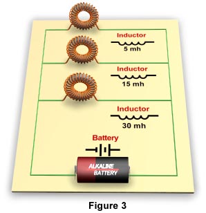
Inductors in Parallel CircuitsA parallel circuit is a circuit in which components are arranged so that the path for the electric current is divided. The excursion in Figure 3 has 3 inductors in parallel.
Placing inductors in parallel always decreases the total inductance of the circuit. If the inductors are shielded, or far plenty apart to foreclose mutual inductance, the total inductance of the circuit tin can be calculated using the following formula:
L T = 1 ÷ (1/Fifty 1 + one/50 2 + i/L 3 . . .)
where L T is the full Inductance in the circuit, and L ane through L three . . . are the inductance ratings of the individual inductors in the excursion.
Using this formula, the total or inductance of the above parallel circuit tin exist calculated every bit follows:
L T = 1 ÷ (1/5 + 1/15 + ane/30)
Fifty T = i ÷ (0.two + 0.066 + 0.033)
L T = 1 ÷ 0.299
50 T = iii.344 mh
The effect of self-consecration in a coil is to oppose any change in current flow in the coil. For example, when voltage is applied to a ringlet, current begins to flow in the coil. This current induces a magnetic field around it. As the field is expanding, a counter voltage, sometimes called dorsum voltage, is generated in coil. This dorsum voltage opposes the main electric current flow. This opposition to current menses is called inductive reactance and is measured in ohms.
The amount of inductive reactance in a circuit depends on the frequency and amount of alternating current, and the amount of inductance. Inductive reactance of a circuit can exist calculated using the post-obit formula:
10Fifty = 2pfL
where TenL is inductive reactance in ohms, 2p is a calculus-derived abiding that is normally rounded off to 6.28, f is the frequency of the practical alternating current in hertz, and L is the inductance of the circuit in henries.
TransformersThe performance of transformers is based on the chief of common inductance. Transformers are used to increase or subtract alternating electric current (AC) voltages and currents in circuits. A transformer ordinarily consists of two coils of wire, electrically insulated from each other, wound on the same core. One coil is chosen the primary coil; the other is chosen the secondary ringlet. The primary coil is the input coil of the transformer and the secondary ringlet is the output coil. When an AC voltage is applied beyond the primary coil, it induces a changing magnetic field in the core. Mutual induction causes voltage to be induced in the secondary gyre.
The number of windings of the main and secondary coils of a transformer determines how the voltage in the circuit is affected. When the number of windings of the chief roll is greater than that of the secondary coil, the induced voltage in the secondary coil is less than the practical voltage of the primary gyre. When the number of windings of the primary whorl is less than that of the secondary coil, the induced voltage in the secondary coil is greater than the practical voltage of the first roll. If the output voltage of a transformer is greater than the input voltage, information technology is chosen a stride-upwardly transformer. If the output voltage of a transformer is less than the input voltage it is called a step-down transformer. Discover the effects of varying voltage inputs and number of windings of a transformer in our Transformer Interactive Java Tutorial.
A stride-upwardly transformer increases voltage. Withal, the increment in voltage comes with a decrease in current. The opposite is true for a step-down transformer. A step-downwardly transformer reduces voltage just increases electric current. This holding of transformers makes them very useful and beneficial for transmitting electric ability over long distances. Stride-up transformers are used at electrical ability generating plants to develop very high voltages. The output current menses is reduced, which profoundly reduces the losses in power due to resistance in manual lines. When the ability reaches consumers, stride-downwards transformers are used to reduce voltage and increase current to appropriate levels for consumer applications.
Applications of InductanceThe properties of inductors brand them very useful in various applications. For example, inductors oppose whatsoever changes in current. Therefore, inductors tin be used to protect circuits from surges of electric current. Inductors are likewise used to stabilize direct current and to control or eliminate alternating current. Inductors used to eliminate alternating current higher up a certain frequency are called chokes.
GeneratorsOne of the most common uses of electromagnetic inductance is in the generation of electrical current. To learn how a generator works visit our Generators and Motors Primer.
Radio ReceiversInductors tin can be used in circuits with capacitors to generate and isolate high-frequency currents. For case, inductor coils are used with capacitors in tuning circuits of radios. In Figure 4, a variable capacitor is connected to an antenna-transformer circuit. Transmitted radio waves cause an induced current to menstruation in the antenna through the main inductor coil to footing.
A secondary electric current in the contrary management is induced in the secondary inductor coil. This current flows to the capacitor. The surge of current to the capacitor induces a counter electromotive force. This counter electromotive forcefulness is call capacitive reactance. The induced catamenia of current through the coil also induces a counter electromotive strength. This is called inductive reactance. So nosotros take both capacitive and inductive reactances in the excursion.
At college frequencies, anterior reactance is greater and capacitive reactance is smaller. At lower frequencies the reverse is true. A variable capacitor is used to equalize the inductive and capacitive reactances. The condition in which the reactances are equalized is called resonance. The particular frequency that is isolated by the equalized reactances is chosen the resonant frequency.
A radio circuit is tuned by adjusting the capacitance of a variable capacitor to equalize the inductive and capacitive reactance of the circuit for the desired resonant frequency, or in other words, to tune in the desired radio station. Our Radio Receiver Interactive Java Tutorial demonstrates how inductor coils and a variable capacitor are used to tune in radio frequencies.
The operation of a metallic detector is based upon the principle of electromagnetic induction. Metal detectors contain one or more than inductor coils. When metallic passes through the magnetic field generated by the gyre or coils, the field induces electric currents in the metal. These currents are chosen eddy currents. These eddy currents in turn induce their own magnetic field, which generates current in the detector that powers a point indicating the presence of the metal. Detect the magnetic fields and eddy currents generated past a metallic detector at our Metallic Detector Java Tutorial.
BACK TO ELECTRICITY AND MAGNETISM HOME
Questions or comments? Send united states of america an e-mail.
© 1995-2022 by Michael W. Davidson and The Florida Land University. All Rights Reserved. No images, graphics, software, scripts, or applets may be reproduced or used in whatever manner without permission from the copyright holders. Utilize of this website ways yous hold to all of the Legal Terms and Conditions set along by the owners.
This website is maintained by our
Graphics & Web Programming Team
in collaboration with Optical Microscopy at the
National High Magnetic Field Laboratory.
Final Modification: Friday, Nov thirteen, 2015 at 02:eighteen PM
Access Count Since March 29, 1999: 268214
Source: https://micro.magnet.fsu.edu/electromag/electricity/inductance.html
Posted by: thomashisre1982.blogspot.com
0 Response to "Does A Inductor Ever Change Magnetic Flux Direction"
Post a Comment